Hi Steve
Yes you could connect the G201X Common to the KFLOP GND on JP4 pin 8 or 9.
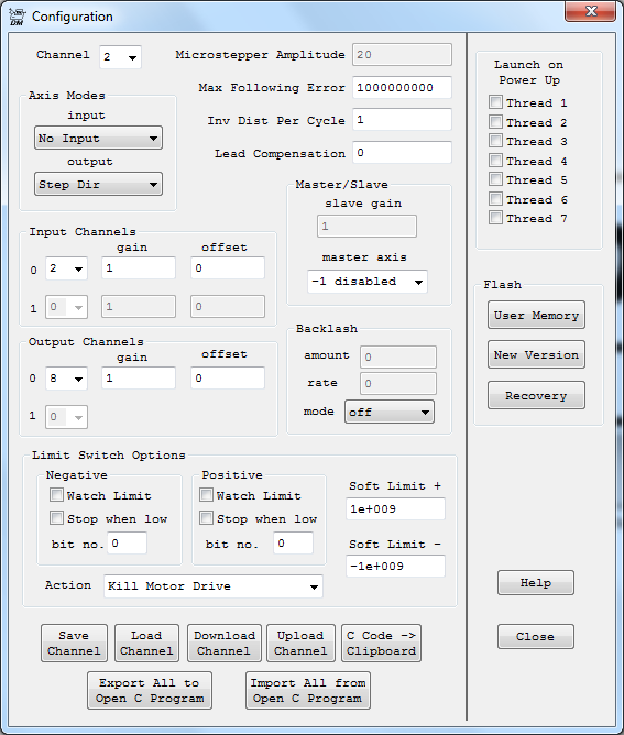
You would want to configure the axis for OutputChan0=8 with FPGA Options:
FPGA(STEP_PULSE_LENGTH_ADD)=63 + 0x40 // set the pulse
time to ~ 4us, mux to JP4 and JP6, and low going step pulse
The outputs in LVTTL Mode drive high (>2.4V) and low (<0.4V).
Since the Geckos are flexible and can be driven high or low it would actually provide more noise margin to put the Gecko common to +3.3V and then use a high going pulse with:
FPGA(STEP_PULSE_LENGTH_ADD)=63 + 0x40 + 0x80 // set the pulse
time to ~ 4us, mux to JP4 and JP6, and high going step pulse
(the Gecko should step on the end of the pulse rather than the beginning to have the max Direction setup time before the step).
HTH
Regards
TK
| Group: DynoMotion |
Message: 9361 |
From: Tom Kerekes |
Date: 3/24/2014 |
| Subject: Re: Kflop JP4 [1 Attachment] |
Hi Steve,
Yes the screen shot looks correct. But "OutputChan2=8" is incorrect and invalid. In some Output Modes a KFLOP Axis Channel can require 2 output devices. They are called OutputChan0 and OutputChan1. Step/Dir Mode only use one Step/Dir Generator device so only OutputChan0 is used to specify
which Step/Dir Generator to use. So in verbose English to :set KFLOP Axis Channel #2's First Output Device Channel0 to use Step/Dir Generator 8 the C code is:
ch2->OutputChan0=8;
Yes add the FPGA setting to your Initialization C Program at the beginning of the main function.
Yes you can add encoder feedback. It really doesn't work well to correct for stepper stalls and missteps. But it does allow you to detect them and stop rather than going on blindly forever possibly causing more and more damage. It also allows recovery from a fault or amplifier disable without loss of position which would
normally require re-homing. In some cases the feedback can be used to observe, plot, and potentially dampen oscillations. If Linear Encoder Scales are used instead of rotary encoders then accuracy may be improved by reducing errors such as leadscrew and backlash errors.
HTH Regards TK
| Group: DynoMotion |
Message: 9362 |
From: Tom Kerekes |
Date: 3/24/2014 |
| Subject: Re: Kflop JP4 [1 Attachment] |
Hi Steve,
Yes the screen shot looks correct. But "OutputChan2=8" is incorrect and invalid. In some Output Modes a KFLOP Axis Channel can require 2 output devices. They are called OutputChan0 and OutputChan1. Step/Dir Mode only use one Step/Dir Generator device so only OutputChan0 is used to specify
which Step/Dir Generator to use. So in verbose English to :set KFLOP Axis Channel #2's First Output Device Channel0 to use Step/Dir Generator 8 the C code is:
ch2->OutputChan0=8;
Yes add the FPGA setting to your Initialization C Program at the beginning of the main function.
Yes you can add encoder feedback. It really doesn't work well to correct for stepper stalls and missteps. But it does allow you to detect them and stop rather than going on blindly forever possibly causing more and more damage. It also allows recovery from a fault or amplifier disable without loss of position which would
normally require re-homing. In some cases the feedback can be used to observe, plot, and potentially dampen oscillations. If Linear Encoder Scales are used instead of rotary encoders then accuracy may be improved by reducing errors such as leadscrew and backlash errors.
HTH Regards TK
| Group: DynoMotion |
Message: 9363 |
From: Steve Klemp |
Date: 3/24/2014 |
| Subject: Re: Kflop JP4 |
Tom, thank you for the clarification, Yes my encoders are linear "glass" scales
Thanks again |
| | | | | |